Central Locking Kaput..

  • Click here to become an Official Member of BMW Club Malaysia Download Form
jarance;555874 said:
woh, there is a lot relays..

curious to know what would the cost would be for SSR retrofit as compare to conventional relay?

btw, can you advise the circuit for the SSR? I am now considering it as a project.

For more info on H-Bridges take a look at Wikipedia.org http://en.wikipedia.org/wiki/H-bridge
Also take a look at the L298 IC from ST Micro (formally SGS Thompson). I think this is the chip that the E39 uses in the PM-BT module for the door locks. Here is my web page for the PM-BT module http://www.bmwgm5.com/PM-BT.htm That chip is not suitable to replace the V23084 relays in the GM5 however. The current rating is too low to handle all the motors paralleled in our cars, especially 4-door ones.

aidilj;555880 said:
Super website. I've read through your site and now am educated and well prepared for this issue. I thought BMW would use some magic in its circuitry, seems not, just relays. I think the hard part in the solid state relay would be the current handling, 15Amps is huge. How long would these relays be energized at a time typically? Do you find any reason why the front window relays are larger than the rear ones?

Thanks. Nope, our E46's get crappy relays. I'm not sure what the E9x series has. They have worst problems with door locks, but, their problem is the crappy actuators. Not sure if they use relays or solid state to drive them. Signals come from "Junction Box Electronics" No longer called a General Module or Central Body Electronics.

The front window relays are a lot beefier than the door locks since the window relays need to do a lot of heavy lifting. Like those huge coupe windows. And the higher duty cycle. Window relays can stay on for almost 10 seconds to close a completely open window.

Yeah, 15 Amps is a lot, but, the duty cycle is small and if you get a good low on resistance MOSFETs the power dissipation is reasonable. For example, take the Infineon ID90N035S4L-02 MOSFET. It has an on resistance of 2.2 milli-ohms. At 15 amps, that's only 0.033 Volts of drop (15 x 0.0022) and only 495mW of power dissipation (15^2 * 0.0022). This part is rated up to 90 Amps (Id) and 30Volts (Vds) in a little TO-252 package for only $1.47 each. But, finding the right MOSFET and wiring it up isn't the tricky part. It's properly controlling the MOSFETs that's the hard part. If you accidently turn on the top and bottom FET on the same side of the H-bridge you can get 12V across 2, 0.0022 Ohms MOSFETS and you could have a shoot through current of over 2000 Amps (12 / (2 x 0.0022)). This would instantly fry both MOSFETs and since semiconductors tend to fail shorted it would continue to draw current even after the controller has turned the MOSFETs off thus frying the parts and most likely the board. Forget about the fuse protecting anything. A standard 30A automotive fuse can last over 10mS at 450 Amps and not blow. There should always be a small dead time between turning one MOSFET off and turning the other MOSFET on. The circuit should also be extensively tested to make sure it doesn't do anything weird during power up and loss of power conditions. One of my first SSR modules, for unknown reasons, released the magic smoke. I think I know why and my new 4-layer SSR modules have not blown up yet.
 
Thanks scott for the reply. So you managed to overcome the timing switching problem. I am still struggling with that circuit.

btw, Thank for the headup on the MOSFets chip. Will certainly look for the datasheet on it.

for layman term, the H-bridge is basically a rectifier bridge working in reverse with switchable control. (Am I talking sense?)
 
More on DC switching using H-bridge configuration:-

http://www.dprg.org/tutorials/1998-04a/

hb6.png
 
initialM;555979 said:
Unker dun to kok ler me stupid cannot understand:sleep:

sorry bro. Got carry away with my posting. It not everyday that I met people like adil and especially scott who are willing to share their knowledge in this forum. :top:


btw, I hear the ghee reputation in the market is contaminated.
 
scottjoh;555961 said:
Yeah, 15 Amps is a lot, but, the duty cycle is small and if you get a good low on resistance MOSFETs the power dissipation is reasonable. For example, take the Infineon ID90N035S4L-02 MOSFET. It has an on resistance of 2.2 milli-ohms. At 15 amps, that's only 0.033 Volts of drop (15 x 0.0022) and only 495mW of power dissipation (15^2 * 0.0022). This part is rated up to 90 Amps (Id) and 30Volts (Vds) in a little TO-252 package for only $1.47 each. But, finding the right MOSFET and wiring it up isn't the tricky part. It's properly controlling the MOSFETs that's the hard part. If you accidently turn on the top and bottom FET on the same side of the H-bridge you can get 12V across 2, 0.0022 Ohms MOSFETS and you could have a shoot through current of over 2000 Amps (12 / (2 x 0.0022)). This would instantly fry both MOSFETs and since semiconductors tend to fail shorted it would continue to draw current even after the controller has turned the MOSFETs off thus frying the parts and most likely the board. Forget about the fuse protecting anything. A standard 30A automotive fuse can last over 10mS at 450 Amps and not blow. There should always be a small dead time between turning one MOSFET off and turning the other MOSFET on. The circuit should also be extensively tested to make sure it doesn't do anything weird during power up and loss of power conditions. One of my first SSR modules, for unknown reasons, released the magic smoke. I think I know why and my new 4-layer SSR modules have not blown up yet.

That is some MOSFET you have there, very low ON resistance. Your calculation make sense and I understand how this could be problem if both FET over postive and negative are switched ON together. Even if the delay is small enough that it doesn't cause a short or smokey FET, the component can be stressed out and causes premature failure.

I don't know if putting resistor at the gate would solve the problem by discharging the pin faster. For the turn ON delay maybe a capacitor? You probably have a better and more elegant solution.

jarance;555965 said:
Thanks scott for the reply. So you managed to overcome the timing switching problem. I am still struggling with that circuit.

btw, Thank for the headup on the MOSFets chip. Will certainly look for the datasheet on it.

for layman term, the H-bridge is basically a rectifier bridge working in reverse with switchable control. (Am I talking sense?)

Jarance, you are correct. H-bridge circuit is mainly used to control and drive motor both ways, forward and reverse. By selectively switching two adjacent transistors, motor will move in one direction. You don't want to turn on transistor A and C or B and D at the same time, this is a short circuit. Some delay would be required when switching motor direction making sure no short circuit happens, the issue that Scott had but you know that already..
 
aidilj;556011 said:
I don't know if putting resistor at the gate would solve the problem by discharging the pin faster. For the turn ON delay maybe a capacitor? You probably have a better and more elegant solution.

That won't work. There needs to be a guaranteed dead time between turn off and turn on of the other device. Simple cap/resistor circuits won't work and are not reliable enough. Plus an inhibit or disable during power up and power down is needed.

Oh, one other thing. The standard H-Bridge shown in post #143 above uses both NPN and PNP transistors which can be easily replaced with N-ch and P-ch MOSFETs. This isn't a problem except that the Infineon MOSFET that I mentioned earlier is an N-channel. Typically P-ch MOSFETs aren't nearly as good as N-Ch one. The On resistance (Rds on) of the best P-channel device in the same package is almost double. To make the high side and the low side symetrical engineers typically use N-ch MOSFETs in place of the P. The problem then becomes the gate of the high side MOSFET must be 10 volts higher than the drain to turn it on fully. Under normal car electronic conditions the drain will be up to 14.4V. So now a some kind of power supply is needed to get that extra 10 volts to ride on top of the high side FET drain.
 
scott, any new update on your I-Bus project?

A small question, can a Rs-485 (2 wired system) be adapted to read the I-Bus data.
 
jarance;556254 said:
scott, any new update on your I-Bus project?

A small question, can a Rs-485 (2 wired system) be adapted to read the I-Bus data.

Well it depends on which IBUS project. I have several. The CD Emulator one is on hold. I just made a huge order of new PC Boards with various projects on one panel. The panel contains 16 individual boards with 11 unique designs. 2 of those designs are for IBUS. One is a IBUS to USB that doesn't use the expensive and hard to get Melexis chip and the other is an IBUS to PIC micro that has 5 discrete outputs (for controlling lights or relays or whatever) and an ePOT for connecting to the wired remote input on Sony or Pioneer head units (IBUS steering wheel controls to control aftermarket head unit. I know it's been done, but, I'd rather do it myself.)

Just reading the I-Bus data to RS-485 shouldn't be a problem. Well actually RS-485 is a problem since 485 is bidirectional and multidrop differential. You need to use RS-422 which is similar in that it's +5V differential, but, not bidirectional and multidrop. There are separate pairs for data in each direction and it's point to point. Below is a schematic of a IBUS to RS-422 interface which uses a National LMS1485, RS-485 differential transceiver chip as a driver only (because I have some of those chips). For the I-Bus side I basically have taken the I-Bus read only interface from my I-Bus reader project http://ibusmodules.com/Reader.htm All you need is the BAT54 diode and the 10K Resistor and connect the RX line to pin 4 (DI) of the National Semi LMS1485 RS-485 transceiver. And pull pin 3 (DE) high. Added schematic
IBUS_RS422.gif
 
Jarance,

From the page, what I undestand is that I-bus is a one-wire serial interface connecting one master to multiple slaves. The bus is an open collector where the master pull it up to 12V, any slave who wishes to sent information needs to just pull it down accordingly. That is on the electrical side of it.

On data transmission, it is a 9600 baud serial interface so a microcontroller with UART function built-in like PICs would be able to communicate with the bus easily. Bit banging is an option if the microcontroller is fast enough or one need to resort to assembly programming.

The slow interface speed explains why my DICE iPod integration may hang sometimes. The master/slave can get confused if too many slaves flooding the wire.

Let me know if any of my understanding is off the mark.

Thanks
 
Aidil, I think scott would be a better person to answer you.

My experience with RS-485 is based on industrial standard. Normally, we have a delicate module based on peer to peer communication. Usually, there should be only 1 master and many slaves. If there are 2 or more masters, then there would be collision alarm. The slaves would not know who to response when both master ask for information from the same slave address.

btw, 9600 bauds rate is very slow. We usually use 19,800 bauds rate minimum.

scott, your input is highly appreciate.

btw, I look at the protocol coding between modbus and I-Bus, the hex coding is quite similar.
 
aidilj;556358 said:
Jarance,

From the page, what I undestand is that I-bus is a one-wire serial interface connecting one master to multiple slaves. The bus is an open collector where the master pull it up to 12V, any slave who wishes to sent information needs to just pull it down accordingly. That is on the electrical side of it.

On data transmission, it is a 9600 baud serial interface so a microcontroller with UART function built-in like PICs would be able to communicate with the bus easily. Bit banging is an option if the microcontroller is fast enough or one need to resort to assembly programming.

The slow interface speed explains why my DICE iPod integration may hang sometimes. The master/slave can get confused if too many slaves flooding the wire.

Let me know if any of my understanding is off the mark.

Thanks

Yup. That's right. A PIC works great.

One more thing which the web site that jarance linked to. The E46 does not have an I-Bus. It only has a K-Bus. Everything that the E39 has on the I-Bus is on the K-Bus with everything else. Here is a list of almost everything on the bus. http://www.bmwgm5.com/E46_K-Bus.htm
 
I found this gadget on Restler web which is what I want for little project going 40 Euro for USB version
and 30 Euro the comm port version (who use comm port nowaday? well, I still do.)

Capture.jpg


Capture_2.jpg
 
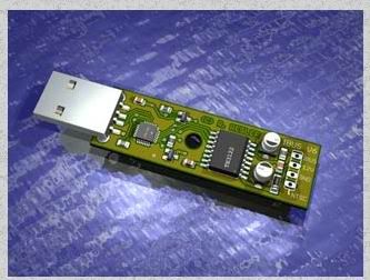
Here is my I-Bus to USB module.
IBUS2USB.jpg


The Resler interface is 46 Euros total (6 Euros is for shipping) which is almost $59 USD. Mine is going to be a good deal less when I finish testing it with all the commonly used software.


Also I have updated post # 150 with a schematic of a I-Bus to RS422/485 read only design.
 
jarance;556461 said:
And if you want the schematic for I_bus to RS-232 comm interface.

Capture_4.jpg

I'm making this circuit. This just came in through the mail.

IMG_2611.jpg
 
Top Bottom